
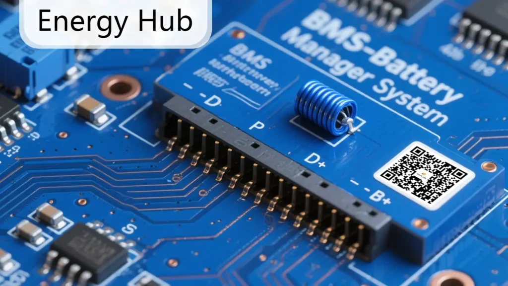
The Seplos BMS interface provides essential communication and control connections for battery monitoring, inverter communication, and system expansion. Understanding each Seplos BMS port definition helps users install and configure the battery system correctly.
For Seplos BMS V2 systems, these interfaces are designed to support reliable communication between battery modules, external devices, and energy storage systems.
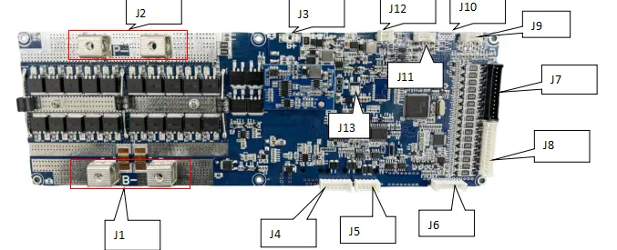
| NO | Function definition | Function description |
| J1 | Total battery negative B- | Use M5 screws to fasten (copper busbar is recommended), the negative terminal of the battery |
| J2 | Output power line P- | Use M5 screws to fasten (copper busbars are recommended) |
| J3 | Battery total positive B+ | BMS power supply, fastened with M3 screws |
| J4 | 485 communication interface | External internal parallel connection and host computer communication interface (Note: 7PIN line) |
| J5 | CAN/485 communication interface | External inverter communication interface (Note: 5PIN line) |
| J6 | LED interface | External reset button and LED lights (capacity light, warning light, operation light) |
| J7 | Battery cell low module acquisition interface | Black row shell, connected to the sampling harness of cells 1 to 8 |
| J8 | Battery cell high module acquisition interface | White housing, connected to the sampling harness of cells 9 to 16 |
| J9 | Display interface | The default power supply voltage of the display is 3.3V (the touch screen is powered by 12V) |
| J10 | 2-way dry contact interface | Control the active balancing board to start |
| J11 | External switch interface | Self-locking weak current switch access port, power supply voltage 12V |
| J12 | Release interface | The output voltage is equal to the total battery voltage |
| J13 | Heating film interface | Heating film interface, maximum output power 200W |
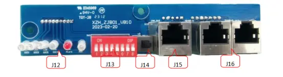
| NO | Function definition | Function description |
| J12 | LED indicator | Running light, warning light, capacity light |
| J13 | Dial address | No function |
| J14 | Power on/off | Press and hold for more than 3 seconds to turn on the device, and press and hold for more than 5 seconds to turn it off. |
| J15 | CAN/485 communication interface | Inverter communication interface |
| J16 | 485 communication interface | Internal parallel and host computer communication interface |
This Seplos BMS interface definition can also be used as a quick reference manual for checking communication ports, wiring connections, and hardware functions during installation and maintenance.
FAQs About Seplos BMS Interface Definition
The Seplos BMS interface provides communication, power, and control connections between the battery management system, inverter, display, and external devices. It allows users to monitor battery status and configure system functions.
Seplos BMS supports communication interfaces such as CAN and RS485, which are commonly used for inverter communication, parallel battery connection, and system monitoring.
CAN communication is mainly used for communication between batteries and compatible inverters, while RS485 is commonly used for battery monitoring, parallel communication, and computer connection.
The Seplos BMS interface definition guide provides detailed information about connector locations, pin functions, and communication purposes for each interface.
Yes. Certain interfaces are designed for parallel connection and system expansion, allowing multiple battery units to communicate and work together.