
The Seplos MASON 280 DIY kit is designed for assembling a 51.2V 280Ah LiFePO4 battery pack using 16 prismatic cells, a compatible BMS, busbars, insulation materials, terminals, wiring, and enclosure components.
Before beginning the assembly, confirm that all components match the MASON 280 kit version and follow the supplied wiring diagram, torque requirements, polarity markings, and safety instructions.
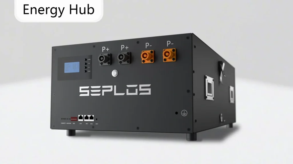
Step 1. Handle and Hasps Installation
- Material: 1 battery pack box and 4 concealed handles
- Tool: electric screwdriver and hexagonal nuts H2.5
Thread the M4 countersunk nuts with the hex H2.5 to the box sink, with the concealed handles’ folding side facing downward.
Set the torque index of the electric screwdriver to 3 and lock the screws until we hear the sound of “da-da”.
Step 2. EVA Tape A/B/C Installation
- Material: epoxy insulation board A/B/C
Rip open the epoxy insulation board A/B/C and stick them to the inner sides of the box
Step 3. Battery Cover Insulation
- Material: polycarbonate, box cover
- Tool: utility knife
After ripping open the polycarbonate, align it with the box margin and stick them together, and expose the screw holes with a utility knife.
Step 4. Battery Cell Placement
- Material: 16 battery cells, 18 EVA-1, 1 fixed plate front, 9 M6 * 14mm Phillip Hex screw Sets(foot fix)
- Tool: Phillip screwdriver, screwdriver with torque index option
Using 16 nominal 3.2V LiFePO4 cells in series creates a nominal 51.2V battery pack. With 280Ah cells, the nominal stored energy is approximately 14.3kWh before usable-capacity limits and system reserve settings are considered.
Put the EVA-1 and cell batteries in the direction shown. After stocking the cells into the box, make sure that side A is slightly lower than the margin or levels with the margin.
Then put another two pieces of EVA-1. Make sure we are having the positive and negative electrodes in the right position.
Set the torque index to 8-9 Nm, and cover the box with a fixed plate front.
Step 5. Top Bracket Insulation
- Material: 2×top plate, 8×M5-8mm Phillip hex screw sets
- Tools: Phillip screwdriver, screwdriver with torque index option
Rip open the EVA-2, and apply it to the side A of the plate top of the module.
After that, fix the module top plate on the cell batteries with M5*10 screws.
Step 6. Battery Cell Connection
- Material: 15×aluminium busbar-1, 12×M4*8mm Phillip hex screw sets, 32×M6 flange nuts
Put the aluminum bus bars as shown. Make sure that we have the maximal contact area between the aluminum bus bar and the cell thread. Put the PCB A/B and tighten it in the order as shown. We lock the string with M6 flange nuts with a torque index of 5 Nm. Connect wire harnesses A and B and measure up the voltage of the module, the neighboring PIN voltage should be around 3.2V.
Step 7. Front plate kits assembling
- Material: 2×battery terminals (yellow), 2×battery terminals (black), 1×front plate, 1×BMS, 1×display screen, 10×M3-8mm Phillip round screw sets
- 1×wire harness C, 1×SF2, 1×SF3, 1×SF5, 1×SF6, 1×SF7, 1×SF8, 1×wire harness A, 1×wire harness B
Fix the battery terminal with a torque index of 1.5-2 Newton meters, BMS with the torque index of 1.5-2 Newton meters, a display screen with a torque index of 0.5-1 Newton meters, a fuse of recommended 7 Newton meters, and copper busbar of torque index of 7 Newton meters. Wrap the display screen wire harness in a cycle and connect the wire harness A, B, and display screen wire harness together.
Step 8. BMS Wiring
- Material: 15×aluminium busbar-1, 12×M4*8mm Phillip hex screw sets, 32×M6 flange nuts
Insulate copper busbar S-F-2, S-F-8, and then connect B’s negative electrode with module A wire harness, module B wire harness, and B’s positive electrode, run a turn-on test by turning on the tact switch, and check if the total voltage is 52V and output current is 0.
Step 9. Battery Pack Fix
Material: 15×aluminium busbar-1, 12×M4*8mm Phillip hex screw sets, 32×M6 flange nuts
Lock the box, box cover, and front plate with a torque index of 4 Nm. And we finish assembling the MASON-280 51.2V 280Ah battery pack.
Final Checks Before Starting the MASON Battery
Before powering on the MASON battery, verify cell polarity, total pack voltage, busbar contact, terminal torque, BMS sampling-wire sequence, temperature-sensor placement, insulation, fuse installation, communication wiring, and enclosure grounding.
Do not connect the battery to an inverter or charger until the measured pack voltage, BMS readings, communication settings, and charging parameters have been confirmed.
Step 10. BatteryMonitor
If the Battery Monitor system shows that the current isn’t 0, calibrate by login in with the account “admin” and password “admin”.
After assembling, the BMS needs to have capacity learning, and this is how we do it:
- Fully charge the battery at a recommended current of 100A
- Set it in the battery protection system with a recommended current of 100A
- Charge the battery until the battery protection disappears with the recommended current of 100A
- The capacity learning is finished.
Please Click for MASON-280 Case kits details.
FAQs About the Seplos MASON 280 DIY Kit
The Seplos MASON 280 DIY kit is a battery enclosure and component solution designed for assembling a 51.2V LiFePO4 battery pack using 16 prismatic cells and a compatible BMS.
A 51.2V 280Ah battery has a nominal energy capacity of approximately 14.3kWh. Actual usable energy depends on the configured depth of discharge, BMS limits, inverter settings, and reserve capacity.
The pack normally uses 16 nominal 3.2V prismatic LiFePO4 cells connected in series. Cell dimensions, terminal type, capacity, consistency, and enclosure compatibility should be confirmed before assembly.
Incorrect BMS sampling-wire order can produce inaccurate voltage readings, alarms, component damage, or unsafe operation. The wires should be connected according to the supplied diagram and checked before the system is powered.
Check the total pack voltage, cell voltages, polarity, BMS readings, communication protocol, inverter compatibility, charging voltage, discharge limits, terminal torque, fuse, and grounding.
Capacity learning may be required so the BMS can estimate SOC accurately. Follow the recommended full-charge and discharge procedure and use the correct current and capacity settings for the installed cells.