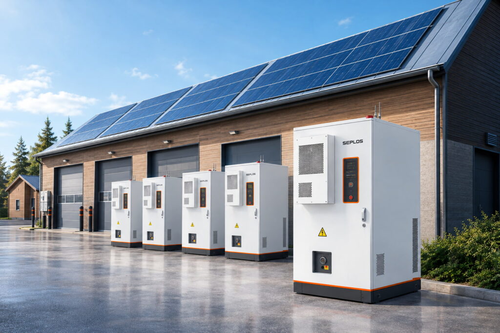
If you are troubleshooting Seplos BMS software or related battery management hardware, the following six issues cover some of the most common startup, monitoring, charging, temperature, and cell-voltage faults users may encounter.
1. The balance board cannot be started
Cause of failure one: The sampling line of the equalization board is connected incorrectly
Note: When assembling the battery, pay attention to the connection of the balanced sampling line
Cause of failure two: The balance board resistor is burned out
Note: Be careful not to insert the black and white row plugs of the sampling line of the equalization board backward.
2. BMS cannot start
Cause of failure one: The B+ line connecting the battery and BMS is not installed. The B+ line is the power line of the BMS. The battery must be connected to start the BMS.
Solution: Check if the B+ line is connected
Cause of failure two: The BMS component MCU was broken down
Note: When assembling, the B+ line should be installed on the BMS board first, and then connected to the battery terminal to prevent the B+ line from being connected to the battery first, and then the line terminal connected to the BMS, accidentally touching the components on the BMS.
How to judge whether the MCU has been broken down: Use a multimeter to check whether the position shown in the picture is normal. If the measurement shows 3.3V, it is normal.
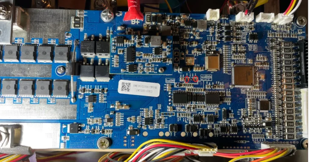
3. BMS sampling abnormality, LED light does not light up
Cause of failure: There is a problem with the resistor on the BMS
Solution: Use a multimeter to measure the corresponding resistor to see if there is any abnormality in the resistance value. If so, the corresponding resistor needs to be replaced.
Normal resistance value:
R228=1206/0R resistance,
R202、R203、R204、R205=0603/0R resistance
Rn1=0805/51R resistance,
N1=NTC thermistor/10K
4. BMS cannot be charged or discharged
Cause of failure: The BMS component is broken down, and the resistance value is Ω level
Troubleshooting: Use a multimeter to measure the charge and discharge of the BMS MOS tube:
G\S pin The resistance value is about 4.2K, which is normal.
G\D pin The resistance value is K level or M level, which is normal.
S\D pin The resistance value is K level or M level, which is normal.
5. Temperature controlled battery 4 appears -50℃
Cause of failure: The temperature control of the sampling board is abnormal.
Solution: The PCB board needs to be replaced. If you need to use the battery temporarily, you can connect to the host computer to turn off the low-temperature protection function.
In Seplos BMS Studio, users can review the relevant temperature protection parameters before making temporary setting changes or confirming whether the sensor data is abnormal. After replacing the PCB board, first check whether the parameters are normal. If they are normal, you need to turn on the low-temperature protection function.

6. During the battery charging and discharging process, one cell appears to be above 4V, and another cell is 2.7- 2.8V.
Cause of failure: A short circuit occurs in the sampling line, causing the BMS to trigger over voltage protection.
Solution: Sampling line needs to be replaced
FAQs About Seplos BMS Software Troubleshooting
A common cause is that the B+ power line has not been connected correctly. If the B+ wiring is correct but the unit still does not start, the MCU or another board-level component may need to be checked.
A multimeter can be used to check the specified MCU test point. According to the troubleshooting procedure in this guide, a reading around 3.3V indicates normal voltage at that test position.
Incorrect or shorted sampling wires can cause false cell-voltage readings. If one cell suddenly appears unusually high while another is much lower, inspect the sampling harness and connections before assuming the cells themselves are faulty.
Check the BMS power components and MOSFET measurements according to the specified resistance ranges. Abnormal resistance values can indicate a damaged component or charging/discharging circuit.
Certain protection parameters may be adjusted for troubleshooting, but safety functions should only be disabled temporarily and for a clear diagnostic reason. After repairs, confirm that the readings are normal and restore the appropriate protection settings.
A -50°C reading can indicate an abnormal temperature-sensing circuit or sampling board problem rather than the actual battery temperature. The PCB, sensor circuit, and related parameters should be checked before normal operation resumes.